Chapter 5
The Cisco Unified Computing
System
The following Understanding Cisco Cloud Fundamentals CLDFND (210-451) Exam Objectives are covered in this chapter:
✓ 3.1 Identify key features of Cisco UCS
- 3.1.a Cisco UCS Manager
- 3.1.b Cisco UCS Central
- 3.1.c B-Series
- 3.1.d C-Series
- 3.1.e Server identity (profiles, templates, pools)
An Introduction to the Cisco Unified Computing System
In this chapter, we move away from the general overview of the cloud and the investigation into the different service and deployment models. You will now learn about the enabling technologies deployed in data centers. The CCNA Understanding Cisco Cloud Fundamentals exam covers a broad array of topics, and one of the most interesting is the Cisco Unified Computing System (UCS). Figure 5.1 shows a 12-rack UCS configuration connected to a pair of fabric interconnect systems.

Figure 5.1 Cisco UCS configuration
Cisco has traditionally had its roots as a routing and switching company with almost an exclusive networking focus. However, over the years as Cisco searched for new sources of revenue, it has been actively expanding into new markets in an effort to diversify its product and services portfolio. This expansion has been accomplished either with internally developed products or with acquisitions. Sometimes, as is the case with the UCS product family, it is a combination of the two approaches that has led to new and interesting product offerings from the company.
In 2009 Cisco publically announced its internally developed line of servers, converged fabric networking products, network adapters, storage, and management software under the UCS label. Internally, the engineering undertaking came to be known by the codename Project California, with many of the subsystems named after cities in California. Project California turned out to be a much larger undertaking than the server product lines that were currently being offered by the major server manufacturers. This was a huge undertaking even for a company the size of Cisco, and it took a long time for most of the industry to really understand the scope of the release. The UCS product line has been hugely successful for Cisco, and in a short amount of time it has taken a significant amount for market share away from the established server vendors. With constant innovation and improvements, the UCS family of products is continually expanding and evolving the cloud technology landscape.
As you could imagine, this was a big shift in focus for Cisco as it had traditionally partnered with the big server manufacturers. Cisco would supply the networking equipment, while companies such as Dell, IBM, HP, and others provided the computing components. Cisco is now competing with these companies, instead of acting in its traditional role as a business partner, and gaining market share from them in the server marketplace.
The one big advantage that was apparent from the announcement was that Cisco did not have any legacy server install base to worry about and could design its UCS product line from the ground up with no migration, integration, or upgrade concerns. This is what is called a greenfield approach and allowed Project California to use the most current architectures, technologies, and convergence design principles available. What a great opportunity this gave the company to completely develop a new product line from a blank sheet of paper! The UCS product family was much more than just bare-metal servers, however; it was designed for virtualization, convergence, and automation technologies from the ground up that are, as you have learned, central to enabling a cloud data center. By utilizing the UCS architecture, cloud service providers could collapse many legacy servers into a smaller number of Cisco UCS servers and realize cost savings in rack space, cabling, power, and cooling requirements in their data centers. Also, with the UCS design and management software, automation and deployment techniques were introduced to greatly enhance the rapid deployment of cloud services.
The UCS family allows cloud providers to have efficient, scalable, and manageable data centers based on converged, open system products. By designing the UCS product line with virtualization in mind, resources can be virtualized and pooled together, which is a primary enabling technology for cloud deployments. The UCS family virtualizes not only the compute operations but also networking and storage all in one integrated system. The lines between servers, networking, and storage began to go away with the UCS family of products. To provide flexible options when designing and implementing a converged network in the cloud data center, Cisco released a wide variety of I/O options for network and server interconnectivity.
The UCS product family is highly integrated and combines computing, networking, and storage into a unified fabric that has centralized management applications for the complete system. The UCS hardware is configured, as you will learn, by policies defined in the management applications that have effectively virtualized the hardware as well as the applications. UCS was designed for automation from the beginning and offers open APIs and high-level tools to configure, monitor, and manage a complete UCS deployment.
Many of the required underlying components were designed to accommodate the virtualization advances made in the cloud data centers. Hypervisors were running on the servers that had the ability to migrate virtual servers from server to server in real time. Failover and deployment of new servers were automated and deployed widely in large public and private cloud data centers. Advanced cloud data center management and automation software systems were developed to enable this advanced capability.
On the server side, the hypervisors allowed the underlying hardware to be hidden from the guest operating systems, but there was still the issue of some very fundamental and limiting server hardware characteristics that were present on the legacy servers. Each server had unique identifiers such as Ethernet MAC addresses, Fibre Channel World Wide Names, the system UUID, very specific BIOS settings, and other configuration parameters that prevented an easy replacement of failed hardware. You could not simply remove the drives from one server and install them into another without expecting a number of addressing and driver issues. This became especially painful if the server replacement was between different models of the same vendor or, much worse, servers between different manufacturers. Server management often meant logging into each server individually to manually make changes or to monitor its operation. With the massive scale of cloud data centers, this was no longer feasible. Legacy servers would traditionally contain at least two Ethernet cables for traditional LAN connections, another LAN cable for management, and two pairs of fiber-optic cables for storage connections. If a data center had 1,000 servers, for example, that would mean more than 5,000 cables just for the server connectivity! These issues were all addressed and mitigated in the UCS products, as you will investigate in this chapter.
The UCS family of products were designed from the beginning for programmability and automation. UCS integrates x86-based server technology with data networking, storage networking, automation, virtualization, and management creating what can best be described as a large pool of racks of servers into virtualized systems that allow for elastic on-demand provisioning for the cloud.
Exploring the Key Features of the UCS Product Family
Before getting into the details of all the products and technologies that make up the UCS product family, we will cover the key features that make up the UCS product line. This is truly a system and not just a collection of products marketed under a common brand name. These systems are designed to all work together as a complete, converged, and unified data center offering. All of the UCS products are configured and managed by centralized UCS management applications that control a large number of physical servers. The servers come in a complete range of form factors and performance levels. The underlying networking fabric is converged with both LAN data and SAN data sharing the same switching fabric that greatly reduces cabling and simplifies the cloud infrastructure design. You will also learn about the management software that ties all of the hardware components into a unified system. These include the Unified Computing System Manager (UCSM) and the UCS Central applications.
To best understand the benefits of the UCS server systems, let’s take a moment to review what was required to implement a new server in the past and, in most cases, still in the present. First, the server needs to be designed around the needs of the operating system and applications running on it. When the server’s processing, memory, storage, networking, and scalability configuration are determined, the purchasing department usually puts the requirements out for bid. Once all of the bids are received, a purchase order is generated, and the order is placed for the hardware. After some time passes, the equipment is delivered at the data center. You then uncrate the systems, complete any additional hardware installations, and mount the server into the rack in the data center. The next steps are connecting power, network, and storage cabling, which, as we discussed, is usually quite a few cables for each server. At this point, weeks may go by, and you still have a long way to go before the server goes live in production. Next up is the configuration of the Ethernet access switches, in other words, the needed VLANs with their associated layer 3 switched virtual interfaces. You may need to add new routing entries and configure the firewall and load balancing policies to complete the networking setup. Also, additional VSAN interfaces for the storage network from the storage engineering group need to be configured. You need to create LUNs and masking and configure SAN zones for Fibre Channel. For Internet Small Computing System Interface (iSCSI), the storage administration group needs to define mappings and storage permissions. When the server is connected to the network, then you can configure all of the BIOS settings needed to allow the server to run most efficiently in a virtualized environment. If local drives are attached, the HDD configurations will need RAID group settings. The boot order, NIC redundancy, and host bus adapter (HBA) configurations all need to be configured.
Now you are to the point where you can install the operating system on the server. This would usually take a fair amount of time to load the image and create the base configuration to get it talking on the network. Then all required patches, required management, and automation software would be installed on top of the operating system. Once all of that is done, it comes time to install and configure the application. Now, imagine having hundreds or maybe even thousands of servers to manage under this approach.
The previous example highlights the configuration and setup issues that the UCS products were designed to reduce or alleviate. Also, it underscores the importance of virtualization and automation to provide rapid server deployments in today’s hyper-scale cloud networks.
UCS Blade Server B-Series
In modern cloud data centers, servers are designed to provide high-density compute resources in the smallest form factor possible and to be as power efficient as possible. Other design considerations include reduced cabling, ease of maintenance, and management. A primary way to achieve these objectives is to mount the servers in a common chassis that shares either a midplane or backplane, power, and cooling. The blade chassis are complete systems that allow power and management of the blade servers inserted in the chassis.
The Cisco UCS blade server family is appropriately called the B-series, and while the central focus will be on the blade servers themselves, we will discuss the complete system and components that make up the B-series, explain why this family is much more than another line of blade server products, and explore what makes them unique in the marketplace. Figure 5.2 and Figure 5.3 show the UCS blade system chassis with server B-series servers installed.

Figure 5.2 Cisco UCS B-series chassis front view

Figure 5.3 Cisco UCS B-series chassis rear view
Blade Server Overview
The UCS B-series combines many different data center technologies into a common unified platform that can be centrally managed and is specifically designed for today’s cloud-based computing operations. Compute, storage, and networking are integrated into a common switching fabric with the UCS B-series platform. The platform is based on a 10 and 40Gb Ethernet converged switching fabric, industry-standard x86 servers that are delivered in a multichassis, highly scalable platform that is managed under a unified management domain.
Each blade server uses the latest Intel Xeon processors and features enhanced highly scalable memory options; they are also designed to be energy efficient. The B-series servers come in a variety of models designed to meet all levels of compute and scalability requirements. The servers implement converged networking adapters for a unified switching fabric that combine both LAN and SAN traffic on the same forwarding plane.
B-Series Architecture
The 5108 blade series chassis is the primary enclosure for the UCS B-series family of products. The 5108 chassis consists of a six-RU enclosure that fits into a standard 19-inch rack. Up to seven 5108 chassis can fit into a standard data center rack for up to 56 servers per rack. The chassis consists of eight half-width or four full-width server slots to accommodate the B-series blade servers.
The chassis contains four front-loaded power supply slots that support a variety of data center power connections including 48 VDC, 200–380 VDC, and both 100–120 or 200–240 VAC power supply options. All four power supplies and eight fan trays are hot-swappable and allow the chassis to continue to operate with either the power supplies or fans removed during maintenance windows.
Each chassis is managed by and connects directly to the 6300 series fabric interconnects that contain the UCS Manager application. The chassis has autodiscovery capabilities and is completely managed by the UCSM application running on the model 6300 fabric interconnects. There is no local management of the chassis. Each slot in the 5108 enclosure supports two 40Gb Ethernet fabric connections to the chassis midplane for a total of 1.2Tb of throughput per enclosure.
All blade servers can be either inserted or removed when the chassis is in operation for noninterrupted service in the cloud data center. The chassis performs constant management and environmental monitoring, and alarm thresholds can be configured to alert operations if a trap metric has been met.
Each 5108 enclosure has two switch fabric extension modules installed that are used to connect to the 6300 fabric interconnects; each fabric module is integrated with the complete system and does not require local configurations. The blade chassis to the fabric interconnects are interconnected, as shown in Figure 5.4, to provide complete redundancy.

Figure 5.4 Fabric interconnects
USC B-Series Models
The B-series of UCS blade servers is a constantly evolving and changing product line that follows advances in technologies with both increments (gen levels) or model releases being offered by Cisco on a regular schedule. For the most current offerings, it is best to check the Cisco website under the Unified Computing topic in the Products and Services section. As new generations of servers are released, the older generations are depreciated to maintenance mode and eventually end-of-life status. You can find up-to-date information on Cisco.com.
The most current and available B-series servers and their key features follow so you can be familiar with what is available in the marketplace:
UCS B22 M3
- Half-width blade (See Figure 5.5)
- 2 Intel Xeon CPU sockets
- 12 memory slots supporting 322GB of memory
- 2 mezzanine slots for 80Gbps total Ethernet/FCOE throughput
- 2 hard-drive bays
- 2 SAS, SATA, SSD hard-drive bays

Figure 5.5 Cisco UCS B22 M3
UCS B200 M4
- General-purpose cloud computing (See Figure 5.6)
- Half-width blade
- 2 Intel Xeon CPU sockets
- 24 memory slots supporting 1.5TB of memory
- 1 mezzanine slot for 80Gbps total Ethernet FCOE throughput
- 2 SAS, SATA, SSD hard-drive bays

Figure 5.6 UCS B200 M4
UCS B420 M4
- Full-width blade (See Figure 5.7)
- 4 Intel Xeon CPU sockets
- 48 memory slots supporting 3TB of memory
- 2 mezzanine slots for 160Gbps total Ethernet/FCOE throughput
- 4 SAS, SATA, SSD hard-drive bays

Figure 5.7 UCS B420 M4
UCS B460 M4
- Large enterprise and cloud applications, designed for memory-intensive workloads used by databases, analytics, bid data, and business intelligence (See Figure 5.8)
- Full-width double-height blade
- 4 Intel Xeon CPU sockets
- 96 memory slots supporting 6TB of memory
- 4 mezzanine slots for 320Gbps total Ethernet/FCOE throughput
- 4 SAS, SATA, SSD hard-drive bays

Figure 5.8 UCS B420
UCS Rack Server C-Series
In this section, we introduce you to the second part of the Cisco UCS server family, the C-series (or Chassis series). We will start with a basic overview of the family of servers, and then you will learn about the architecture of the server series platforms. Finally, we will end the section with a look at eight different models in the C-series of chassis servers.
The Chassis Server Overview
In addition to the blade servers that Cisco released with Project California, Cisco introduced a complete line of chassis, or rack-mountable servers, called the C-series. These servers feature a range of models that are designed for both general and specific uses. They are all based on industry-standard components such as the Intel Xeon family of CPUs. All servers are designed to be operated as a virtualized server with a hypervisor installed and supporting a large number of virtual machines or with the operating system installed directly on the server.
The C-series product family is constantly evolving, with new versions and models being released regularly from Cisco and older models going through the end-of-life process. It is advised to check the Cisco.com website for the latest and most up-to-date information on the server family.
C-Series Architecture
The UCS C-series design is based on the industry-standard server architecture found in all Intel-based servers found in the marketplace today. There will be a variety of options between each server model for CPU slots, memory slots, capacity, the types of interface cards supported, and hard drive slots available. Cisco also supports the Cisco Extended Memory Technology for increased RAM capacity that allows for large pools of memory often required in a virtualized cloud data center.
The servers offer out-of-band management with both Ethernet and serial ports used to remotely manage the servers. Also, with the use of fabric extenders, the C-series servers can be managed as a domain using UCSM, the same manager application that is used to control the B-series blade server. However, using UCSM is not a requirement, and the C-series servers can operate in a stand-alone environment.
USC C-Series Models
The C-series of the UCS server product line is also constantly evolving as new models are released and existing servers are upgraded to keep pace with new technology introductions and advances. Just like you learned with the B-series, the C-series will release new versions of existing models with new generations such as Generation 1, Generations 2, and so forth. The nomenclature will be in the format of Cxx-M1, M2, M3, and so forth. The Cisco.com website will have the latest information on server models and releases.
We will introduce the current models in the C-series and then give a list of the key features so you can be familiar with what is currently available.
UCS C22 M3
- Designed for a wide range of scale-out applications (See Figure 5.9)
- 1 rack unit high
- 2 Intel Xeon 8-core CPU sockets
- 12 memory slots supporting 384GB of memory
- 2 PCIe slots
- 8 SAS, SATA, SSD hard-drive bays
- Redundant hot-swappable power supplies

Figure 5.9 UCS C22 M3
UCS C24 M3
- Entry-level virtualizations, expandability, web applications (See Figure 5.10)
- 2 rack units high
- 2 Intel Xeon 8-core CPU sockets
- 12 memory slots supporting 384GB of memory
- 5 PCIe slots
- 8 SAS, SATA, SSD hard-drive bays
- Redundant hot-swappable power supplies

Figure 5.10 UCS C24 M3
UCS C220 M3
- High-density general compute platform (See Figure 5.11)
- 1 rack unit high
- 2 Intel Xeon 8-core CPU sockets
- 16 memory slots supporting 512GB of memory
- 2 PCIe slots
- 8 SAS, SATA, SSD hard-drive bays
- Redundant hot-swappable power supplies

Figure 5.11 UCS C220 M3
UCS C220 M4
- High-density general compute platform (See Figure 5.12)
- Entry-level virtualizations, expandability, web applications
- 1 rack unit high
- 2 Intel Xeon 8-core CPU sockets
- 24 memory slots supporting 512GB of memory
- 2 PCIe slots
- 8 SAS, SATA, SSD hard-drive bays
- Redundant hot-swappable power supplies

Figure 5.12 UCS C220 M4
UCS C240 M3
- High-density general compute platform (See Figure 5.13)
- 2 rack units high
- 2 Intel Xeon CPU sockets
- 24 memory slots supporting 768 GB of memory
- 5 PCIe slots
- 12 SAS, SATA, SSD hard-drive bays
- Redundant hot-swappable power supplies

Figure 5.13 UCS C240 M3
UCS C240 M4
- High-performance and scalable compute platform used for big data, collaboration, virtualization, storage, and high-performance computing applicators (See Figure 5.14)
- 2 rack units high
- 2 Intel Xeon CPU sockets
- 24 memory slots supporting up to 1TB of memory
- 6 PCIe slots
- 24 SAS, SATA, SSD hard-drive bays
- Redundant hot-swappable power supplies

Figure 5.14 UCS C240 M4
UCS C420 M3
- High-performance and scalable compute platform used for big data, high storage density applications for compute, I/O, storage, and memory-intensive stand-alone and virtualized applications (See Figure 5.15.)
- 2 rack units high
- 4 Intel Xeon CPU sockets
- 48 memory slots supporting up to 1.5TB of memory
- 4 PCIe slots
- 16 SAS, SATA, SSD hard-drive bays
- Redundant hot-swappable power supplies

Figure 5.15 UCS C420 M3
UCS C460 M4
- Very high-performance server for compute and memory-intensive mission-critical and virtualized applications (See Figure 5.16)
- 4 rack units high
- 2 to 4 Intel Xeon CPU sockets
- 96 memory slots supporting up to 6TB of memory
- 10 PCIe slots
- 12 SAS, SATA, SSD hard-drive bays
- Redundant hot-swappable power supplies

Figure 5.16 UCS C460 M4
UCS Interconnect and Unified Fabric Products
The 6300 fabric interconnects act as the central control and interconnection point for the USC products. Operating in a pair, the 6300 is directly connected to each 5108 blade chassis and also the outside network in the cloud data center. As you will learn, the fabric interconnects play a critical role in the operation of a UCS deployment.
They offer up to 320Gbps of bandwidth per connected blade server chassis, with a total of 2.56Tbps of switching capacity. The fabric interconnects reduce network cabling and serve as the compute platform for the UCS Manager application. Redundant cooling fans, power supplies, front-to-back airflow, and rear cabling are standard features along with out-of-band management interfaces.
The fabric interconnects serve as the central management point for a cluster of blade server chassis. They also act as the interconnection point between the UCS domains to the rest of the cloud data network. The fabric interconnects are operated in active pairs for redundancy and come in either 24- or 32-port models offering both 10G and 40G LAN interfaces. The interfaces support Ethernet for data and either Fibre Channel over Ethernet or iSCSI for storage traffic. The converged fabric architecture enables both LAN and SAN data to simultaneously share the same forwarding plane. The unified fabric reduces the NICs, HBA switches, and cabling required by eliminating the need for separate LAN and SAN interfaces. Fibre Channel traffic is encapsulated into Ethernet frames, and the servers utilize converged network adapter technology to further reduce the number of interfaces required per blade server.
The embedded UCS Manager can manage from one to twenty 5100 series blade chassis as well as the C-series servers that we will introduce later in this chapter.
The fabric interconnects operate in a redundant configuration that allows for two converged network paths from each individual blade server chassis to the cloud data center network, as shown in Figure 5.17. It is important to understand that while the fabric interconnects switching fabric is active on both switches, the UCS Manager application that also resides in each fabric interconnect operates in an active standby mode. During operation, the cluster is designed for resiliency and continuous operation. The UCS cluster can continue to operate with a failed 6300 interconnect. In fact, B-series server cards can be removed and inserted (as well as the power supplies and fan trays in the 5108 chassis). Changing the fabric interconnect switching mode from Ethernet to Fibre Channel will cause service disruption and should be performed only during initial setup.

Figure 5.17 Redundant fabric interconnect modules
Cisco Data Center Unified Fabric Interconnects
The current shipping model on the UCS fabric interconnects is the 6300. There remains a large installed base of 6100 and 6200 interconnects, but both models have been discontinued by Cisco. The exam will focus on the model 6300 fabric interconnect family.
Currently there are three products in the 6300 family, and each is designed to support a specific use case and features different form factors and interface speeds. They are similar in that each model hosts the same UCS Manager application needed to control and manage the complete UCS domain. We will outline the different models to get you up to speed on this critical UCS component.
UCS 6332 Fabric Interconnect
- The 6332 rack mount fabric interconnects operate in a pair, and the UCS Manager application resides in the 6332. They serve the function of being the central management point of the UCS domain (See Figure 5.18.)
- 32 40Gbps interfaces that can be configured for 4×10 breakout requirements
- High-density, line-rate Ethernet and Fibre Channel over Ethernet support
- Supports up to 160 UCS C-series rack and UCS B-series blade servers
- Supports up to 20 5108 B-series chassis
- 2.56Tbps throughput
- Redundant power

Figure 5.18 Cisco UCS fabric interconnect model 6332
UCS 6332-16UP Fabric Interconnect
- The 6332-16UP fabric interconnects extend the functionality of the 6332 model with the addition of 16 unified ports that can be configured for either Ethernet or Fibre Channel interfaces. The unified ports allow for converged LAN and storage traffic in the UCS domain. External to the domain, the 6332-16UP offers Fibre Channel interfaces to interconnect to the cloud SAN network. These 16 ports have the flexibility to be configured either as Ethernet or as Fibre Channel. Since changing the modes of the unified ports requires a reload of the fabric interconnect, the mode of the interfaces is usually only set at the time of the initial installation (see Figure 5.19).
- Twenty-four 40Gbps interfaces that can be configured for 4×10 breakout requirements
- Sixteen 1Gbps or 10Gbps and Fibre Channel over Ethernet or 4Gbps, 8Gbps, and 16Gbps Fibre Channel unified ports
- High-density, line-rate Ethernet and Fibre Channel over Ethernet support
- Supports up to 160 UCS C-series rack and UCS B-series blade servers
- Supports up to 20 5108 B-series chassis
- 2.43Tbps throughput
- Redundant power

Figure 5.19 Cisco UCS fabric interconnect model 6332-16UP
UCS 6324 Fabric Interconnect
- The 6324 is also known as UCS mini. It is designed to insert directly into the 5108 blade chassis for smaller installations that do not require external rack-mounted fabric interconnects such as the 6332 and the 6332-16UP models (see Figure 5.20).
- Inserts as a line card into the 5108 enclosure
- The UCS Manager application resides in the 6324.
- Four 1Gb to 10Gb Ethernet and Fibre Channel over Ethernet external interfaces
- One 40G (4×10G) external interface
- 2Gbps, 4Gbps, and 8Gbps Fibre Channel interfaces
- Supports up to 20 UCS C-series rack and UCS B-series blade servers
- Sixteen 10Gbps interfaces to servers in the 5108 chassis
- 500Gbps throughput

Figure 5.20 Cisco UCS fabric interconnect model 6324
Combining Data and Storage on the Same Switching Fabric
One of the key features of the UCS switching fabric is that of convergence of dissimilar network traffic. Convergence refers to the ability of the switching fabric to support both LAN data traffic and SAN storage traffic on the same forwarding plane. With a converged network fabric, there is a reduction in the amount of hardware required as multiple networks are collapsed into one unified switching architecture. Also, cabling to the servers is greatly reduced as a single high-speed Ethernet connection to the server supports both LAN and storage traffic.
This design approach eliminates the need for a separate Ethernet network for LAN data and another network for SAN or storage traffic in and out of the UCS clusters. The B-series and C-series servers support converged network adapter cards that allow for convergence into the servers themselves, eliminating the need for separate LAN and SAN cards to be installed in the servers. The Converged Network Adapter (CNA) connects to the unified fabric on the 5108 backplane or by using 10Gbps or 40Gbps Ethernet to the chassis servers. However, and this is where the magic takes place, the operating system running on the servers is fooled into thinking there are two individual interface cards, one for LAN traffic and a second for SAN traffic. This approach reduces cabling and interface ports and the need to manage separate networks in the UCS products. This is the primary objective and feature of using a converged network switching fabric.
UCS Manager
The Unified Computing System Manager (UCSM) is the central configuration and management point for UCS products. UCSM is an application that runs on the 6300 series fabric interconnects in a hot-standby or active/standby mode. The UCSM combines the management functions of networking, storage, and compute into a central application that can be configured with a Java-based graphical interface, a CLI, or XML APIs that allow machine-to-machine automation, configuration, and management from third-party vendors. Up to 20 5108 B-series chassis can be managed as well as the C-series UCS servers. UCSM provides a common management platform that consolidates individual applications and utilities that were commonly needed in the past to manage individual blade racks, storage, networking, and compute. All UCS products are designed to be managed under the UCSM umbrella for a consolidated point of configuration. This allows you to quickly scale, integrate UCS into the cloud data center’s automation systems, pool resources, allow enhanced virtualization technologies, and commission or decommission servers automatically for rapid deployment.
The UCS Manager allows for the virtualization of all compute hardware, networking, and storage in the system, and by treating these as virtualized pools, you can create on-demand, highly scalable service offerings in the cloud. Compute services can be preconfigured or provisioned on demand.
At the beginning of this chapter, we discussed the traditional model of bringing servers online and discussed the limitations you encounter when replacing server hardware. The MAC, WWN, and UUIDs were all hard-coded on each server, and there were also BIOS and storage configurations that needed to be contended with. This was all taken into account when UCS was developed, and the addressing issues of the past have all been virtualized and are now managed with UCSM. BIOS settings, MAC addresses, WWNs, and BIOS settings are all stored in UCSM as configuration objects instead of on the server itself. With the UCS, replacing server hardware is as simple as connecting the replacement server and having UCSM automatically download the configuration with all of the required parameters to the new server. Zero-touch provisioning has become a reality. Service profiles allow you to virtualize what used to be hard-configured on a server, and those profiles can be dynamically applied to the UCS hardware.
Every configurable item in the UCS product family is an object; there is an autodiscovery system that scans for changes in the environment and updates the configuration object database.
Profiles and templates allow for ease of use and replication in the data center by creating templates for use cases of service offerings and then replicating the template across many devices in the UCS servers.
Role-based administration allows for the allocation of resources and security by defining roles and applying users to those roles. For instance, you can define server administration, networking, and storage roles for the cloud operations staff. New roles can be created, and existing roles can be modified to meet the requirements of your cloud operations center.
The UCSM is designed to be an open management system. The architecture uses XML APIs, and Cisco publishes the APIs to allow third-party companies to write automation and orchestration code as well as for integration into their internal products. Cisco offers scripting tools and software development kits to assist companies in creating application interconnects to the UCS system.
UCSM supports ongoing maintenance and operations with the support of alarm and usage reporting. Thresholds can be defined that allow for automation systems to make changes when scaling up or out for on-demand cloud service offerings. Internal maintenance can be scheduled for automated firmware updates that are periodically offered by Cisco in pretested bundles that mitigate the risk of firmware interoperability issues.
The UCSM is a software application that runs on the 6300 fabric interconnect platforms. The UCS Manager is the glue that ties all of the UCS components together under a single management application, as shown in Figure 5.21. All blade and rack-mount servers are managed from the UCSM domain using a graphical user interface, command line, XML, or APIs. The server, storage, and networking configuration functions are included with the applications and with the integration of these disparate technologies. The UCSM offers rapid deployment in near real time, which is critical for on-demand rapid provisioning found in cloud operations. No longer do you need to have the server group make their needed configuration additions and then the follow up with the networking department connecting the servers to the network and configuring all VLANs, routing, switched layer 3 interfaces, quality of service, and so on. Traditionally, the storage group would also need to configure and connect the SAN to the servers. This was usually a manual process prone to errors and long delay. With the UCSM, you can now complete all of these tasks with preconfigured policies or with the help of higher-level cloud orchestration and provisioning tool interconnects using XML API calls to the UCS domain via UCSM.
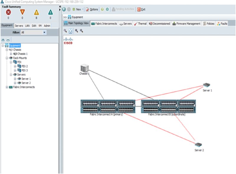
Figure 5.21 Cisco UCS Manager
The management software can be partitioned for use by multiple discrete and separate entities.
UCSM GUI
When accessing the GUI, a standard web browser can be used for HTTP/HTTPS web access to the UCS Manager application. Then the web screen loads, and you will be able to select the UCSM Java application to download and run on your local system. The UCS Manager client is a Java based application that runs on the remote client to access UCSM. A standard username and password are required to access the user accounts defined in the application. Figure 5.22 illustrates the UCSM graphical interface.

Figure 5.22 UCS Manager interface
UCSM Use Cases
The UCSM controls, monitors, and configures the complete Cisco Unified Computing System environment. The application is the most critical component in the UCS. Without its operations, the complete UCS domain would not be able to be controlled. The use cases for the system are to provision, monitor, and manage the UCS deployment. You are familiar with the Java-based graphical interface for human interactions. However, there are also the XML APIs that Cisco has made public that allows for machine-to-machine communications. The use of the APIs enables third-party developers and even Cisco to write applications that communicate directly with the UCSM. This allows for rapid provisioning, monitoring, and applications such as billing and on-demand provisioning. Statistics can be collected for a dashboard type of operational screens. Trouble ticketing, security, and different service model deployment applications all use the UCSM as the interconnect to each UCS domain.
UCS Central
For large cloud installations, the UCSM management limit of 20 chassis or 160 servers can be reached, limiting scalability. However, further expansion can be accommodated using the UCS Central management application that controls multiple UCSM domains. UCS Central offers multi-UCS node management.
The UCS Central application is a global management platform that allows administrators to define polices that will then be applied to a number of UCS Manager systems that are each managing an individual UCS domain.
UCS Central is a configuration tool, serves as the central repository for configuration objects, is a workload management tool, and provides an information dashboard.
The configuration tools provide functions such as monitoring, changing the configuration of each individual server or complete systems, updating the servers’ firmware and drivers, and providing backup and restore operations and user-based roles. Information displayed as a dashboard function provides information such as statistic counters, critical event logging, fault monitoring, and device inventory. The object storage repository stores all information on ID pooling and offers a centralized database of IDs selected from global pools with usage statistics and ID conflict resolution. Pools can be used for UUIDs for server identification, PWWNs for Fibre Channel adapters, Ethernet MAC addresses and IP addressing profiles, policies, VLANs, VSANs, and a large number of system configuration objects. The workload manager concerns topics such as changes and moves occurring in the domain as well as system definitions.
Global policies are defined on the UCS Central system and pushed out systemwide for a centralized enforcement and consistency point that includes maintenance, firmware management, backups, and exports. Global configurations are defined in the UCS Central system using the policy manager and then applied to each UCS domain. Domains can be grouped together to match a public cloud region or availability zone but still maintain a centralized management system.
UCS Central runs as a virtual machine application that is external to the fabric interconnects where, as you recall, the UCS Manager applications reside. UCS Central is installed on a hypervisor and accessed by either the APIs or a GUI interface.
The architecture of UCS Central allows for a programmable platform that can accept configuration parameters from systems above it (northbound) and push the polices to the UCS products below it (southbound).
The northbound interface uses the eXtensible Markup Language or XML as its API. This allows for an open system that any vendor can write interfaces to from their own applications as well as internally developed systems such as portals, management systems, and compliance adherence. Scripting languages can be written for machine to UCS Central interfaces, and there is a Java-based user interface similar to that of the UCS Manager. Companies that integrate their applications with UCS Central include VMware, IBM, EMC, Computer Associates, HP, and Microsoft, to name just a few.
UCS Central GUI
The UCS Central graphical interface is similar to the UCSM and is illustrated in Figures 5.23 and 5.24. The GUI is accessed from a web browser to allow for remote access. Configuring and managing a complete UCS domain using UCS Central is beyond the scope of the Understanding Cisco Cloud Fundamentals exam, and all examples are for information only. The Cisco data center certification covers UCSM and UCS Central in more extensive detail.

Figure 5.23 UCS Central main screen

Figure 5.24 UCS Central graphical interface
UCS Central Use Cases
UCS Central is required when you exceed the operational limits of the UCS Manager application. Each UCSM can manage up to 160 UCS servers and 20 5108 blade chassis. UCS Central allows for many UCSM systems to be controlled by one UCS Central controller.
Other common use cases include using the application as a central repository of information in a multidomain UCS environment. Statistics, firmware updates, object pools, statistics, and configuration policies are all stored in the UCS Central application for the global installation and pushed down to each domain’s UCSM application. This consolidates many domain configuration points into one central control point.
Server Identity (Profiles, Pools, and Templates)
In this section, we provide an introduction to the basic UCS configuration concepts as they relate to server configurations. This section is intended to make you familiar with the basic concepts for server identity, including profiles, templates, and pools.
UCSM Configuration Concepts
The exam blueprint for the Understanding Cisco Cloud Fundamentals exam expects you to be familiar with the UCSM application and to be aware of the general UCS configuration concepts that you will learn about in this section. It is important for us to be clear that this is a large topic that whole books and training courses cover exclusively. The UCS configurations are large and sometimes complex. For the CCNA Cloud certification, it is not expected that you know all of the thousands of configuration options available.
The UCSM application can be extensive and detailed; many resources can be found online for specific UCSM operational issues that are beyond the scope of the Understanding Cisco Cloud Fundamentals exam.
Understanding UCS Profiles
The configuration of UCS components can be a large undertaking given that there are so many configuration points, servers, interconnects, network adapters, LANs, SANs, and many other objects to be configured. It can at first seem overwhelming. However, Cisco has designed the application to allow configurations to be placed into groups, or profiles, and makes those profiles reusable by all systems in the UCS domain. A large number of configuration objects are combined into a profile and stored in the UCS Manager, which greatly simplifies the configuration process. Each UCS server in a domain has to be associated with a profile to operate as it needs a basic configuration like all servers and network equipment. Only one profile can be assigned to a server at a time, which makes sense when you consider that it can have only one configuration applied to it at any given time.
When administering a UCS server, all configuration changes are applied to the profile. As shown in Figure 5.25, all servers associated with that profile will automatically inherit the configuration changes. Figure 5.26 shows a more detailed policy configuration where the server’s boot order is defined. As you can see, there are a large number of configurations to define in a policy. This applies not just for the server itself but for all attached controllers, interface cards, and converged fabric connections.

Figure 5.25 UCS service profiles

Figure 5.26 UCS service boot profile
With the rapid growth of cloud data centers, rapid hardware provisioning becomes an important feature to facilitate the timely installation of UCS hardware. The UCSM allows you to define profiles for servers that are yet to be installed. The system can be preconfigured, and when the server arrives and is inserted into the system, it will automatically download its profile and configure itself for use in the cloud data center.
Service profiles are created using any of the standard user interfaces including the GUI, CLI, or XML API.
Examples of profile objects to be configured for the fabric interconnects include the following:
- Virtual interfaces
- Uplink selection
- VLAN tagging
- VSAN selection
- QoS settings (for LAN-based SAN)
UCS blade chassis service profile objects include the following:
- Server identifier
- MAC address
- WWN addresses
- Firmware packages
- BIOS settings
- Boot order
- Management IP address
Understanding UCS Pools
Pools are used in UCS configuration setups when a range of identifiers is required but when it is desirable to abstract them from the underlying hardware. For example, each domain will require a pool of Ethernet MAC addresses to allocate to Ethernet LAN NIC cards on each server. Pools are defined in UCSM and are assigned to devices in the domain as needed. These pools can then be assigned to a service profile to allow the server to pull addressing as required. Figure 5.27 shows the GUI of the UUID pool configuration screen.

Figure 5.27 UUID pool configuration screen
Pools can be created for many objects, including the following:
- UUID: A server universally unique identifier assigned to servers
- MAC: Media Access Control addressing used to identify LAN NIC adapters
- nWWN: Node World Wide Name for Fibre Channel node identification on a host bus adapter
- pWWN: Port World Wide Name for Fibre Channel host bus adapter port identification
- Management IP: A pool of IP addresses available to be assigned per server for management access
Pools can also be created for servers, where a number of servers share common characteristics such as memory, CPUs, or network bandwidth that are grouped into a pool and all assigned the same policies.
Understanding UCS Templates
Templates group configuration objects together that form a base configuration for a server in the UCS product family. Templates allow you to define a group of policies, pools, and other objects into a template. The UCSM provides a configuration wizard that is used to build a template.
The wizard allows you to include the following in a template:
- Identity service profile UUID pool assignment
- Networking options such as virtual NICs, MAC address pools, and many other options
- Storage polices for disk host bus adapter configurations and SAN configurations
- Fibre Channel SAN zoning information
- vNIC and vHBA configurations to create on the servers
- vMedia information to define storage shares such as NFS, CIFS file systems, and HTTP/HTTPS access, and any virtual media mounts such as hard drives and CDs
- Server boot order to define the preferred order of devices to search to locate the boot loader
Figure 5.28 and Figure 5.29 illustrate the server configuration screens in UCSM. As you can see, this is an extensive and detailed application that, over time, becomes intuitive to operate.

Figure 5.28 Server pool configuration screen

Figure 5.29 General server configuration screen
Summary
This chapter moved away from cloud theory and models and covered the Unified Computing System. UCS is Cisco’s line of server products that introduced a completely new server platform than was currently offered in the marketplace.
We started out with an introduction to the complete UCS setup, the components that are used, and how they interconnect with each other. The fabric interconnects are the heart of the system and are the interconnection point to all blade chassis, the external data, and storage networks, and you learned that the fabric interconnect is the host-processing platform for the UCS Manager configuration and management application.
Then you learned about the B-series architecture of blade compute systems, you learned about the 5108 blade chassis, and you became familiar with the current models of blade server hardware.
The chassis servers in the UCS product lineup are the C-series, and you saw many of the current models and what their primary use cases are. You learned that the system is managed by the UCS Manager application for each domain, and for large cloud deployments the UCS Central application is used to manage multiple UCS domains.
The chapter ended by taking a deeper look at the UCSM and UCS Central applications, and you were introduced to the basic configuration concepts of pools, policies, templates, and profiles.
Exam Essentials
Explain what the UCS family of products are. Know all the primary components in the UCS family such as the fabric interconnects, the 5108 chassis, B and C-series servers, and the UCS Manager and UCS central applications.
Define the fabric interconnect converged networking capabilities. The 6300 fabric interconnects support native Ethernet frames and iSCSI storage data over Ethernet, and the UP or unified ports can be configured for either Ethernet or Fibre Channel but not both at the same time.
Understand the UCS configuration protocols supported. The UCS Manager and UCS Central applications support XML APIs, a command line, and graphical interface.
Know the basics of the UCSM configuration concepts. Understand what profiles are and where they are used. Know that server profiles are a collection of configuration objects that get applied to the UCS server instead of directly configuring the server. Many common addressing requirements are now virtualized in the UCS products, and the addresses are no longer physically applied to the server. With the UCS setup, pools are created for such objects as UUID, MAC, WWN, IP addresses, and others that are then dynamically assigned to systems in the UCS domain.
Written Lab
Fill in the blanks for the questions provided in the written lab. You can find the answers to the written labs in Appendix B.
- The UCS converged switching fabric combines which two
technologies into one shared forwarding plane?
___________ and ___________ - In large cloud installations with multiple regions and availability zones throughout the world, the ___________ ___________ application is used to manage multiple domains.
- UCSM management access methods include ______ ______ ______ or ______ interfaces.
- The ______ UCS chassis provides redundant power and cooling with eight half-width server slots.
- Logical groups of device addressing that are allocated to servers from UCSM are called what?
Review Questions
The following questions are designed to test your understanding of this chapter’s material. You can find the answers to the questions in Appendix A. For more information on how to obtain additional questions, please see this book’s Introduction.
-
Where are specific UCSM boot settings used by a server stored?
- Pools
- Profiles
- BIOS
- UUID
-
World Wide Names are primarily used for what function?
- LUN masking
- Zoning
- HBA addressing
- iSCSI target mapping
-
UCS Manager API communications are based on what structure?
- Perl
- JSON
- XML
- Python
-
Which UCS application manages a cluster of domains?
- UCSM
- Java
- XML
- UCS Central
-
6332 fabric interconnect downlinks can operate at which speeds? (Choose two.)
- 1Gbps
- 10Gbps
- 40Gbps
- 100Gbps
-
Fabric interconnects do which of the following? (Choose three.)
- Connect 5108 chassis into a domain.
- Virtualize server systems.
- Host the UCS Manager.
- Provide a converged switching fabric.
- Host the UCS central management application.
-
Multiple UCS domains are managed by which application?
- JSON
- UCS Manager
- XML
- UCS Central
-
UCSM operates in which mode?
- Primary/primary
- Active/standby
- Cluster
- Network function virtualized
-
What is the maximum number of full-width servers that can be installed in a 5108 chassis?
- 2
- 4
- 6
- 8
-
The UCS family of products includes which technology areas? (Choose three.)
- Networking
- Storage
- Firewall security
- Intrusion detection
- Servers
- Load balancing
- Cloud orchestration
-
The 6300 converged fabric operates in which mode?
- Active/passive
- Active/standby
- Active/active
- On-demand provisioning
-
What are the main features of the UCS product line?
- 10Gb converged fabric, decentralized management, optimized for virtualization, individual device configuration, isolated LAN and SAN networking
- 10Gb converged fabric, centralized management, optimized for virtualization, centralized configuration profiles and templates, variety of I/O options
- 1Gb Ethernet switching, centralized management, optimized for virtualization, variety of I/O options
- 10Gb converged fabric, centralized management, proprietary APIs
-
What is a layer 3 network interface called?
- SVI
- UUID
- FC
- HBA
-
UCS C-series servers support which types of local storage? (Choose three.)
- Flash
- SSD
- SAS
- SATA
- DAT
-
A 6332-16UP unified port supports which two protocols?
- JSON
- Fibre Channel
- Fabric path
- Ethernet
-
Which UCSM feature assigns configurations to a B22M3 server?
- pWWN
- Global policy
- BIOS boot order
- Server profile
-
What can pools be created for? (Choose four.)
- UUID
- MAC addresses
- XML addresses
- Management IP addresses
- IaaS server groups
- Hybrid cloud availability zones
- Fibre Channel worldwide names
-
The UCS Central application configures what southbound service?
- SaaS
- Python
- SNMP
- UCSM
-
What objects can be configured in a fabric interconnect with the UCS Manager? (Choose four.)
- VSAN
- Uplinks
- Boot order
- WWN address
- VLAN tagging
- UUID
- QoS settings
-
What are the primary differences between the B-series and C-series products? (Choose three.)
- Internal storage
- Rack density
- Processing capacity
- Number of interface slots